
Motorcycle auxiliary lights: how to wire them with a relay, step by step

You fit a pair of auxiliary lights, connect them to a handlebar switch and they work. Until one day the switch gets hot, the lights flicker or they simply stop coming on. The problem is almost always the same: the current for the lights is running through the switch. This guide explains how to do it properly.
How much a light draws
The current a light needs is easy to work out: current = power ÷ voltage. With approximate figures at 12 V:
- 55 W halogen: about 4.6 A. A pair, about 9 A.
- 20 W LED: about 1.7 A. A pair, about 3.5 A.
Always check the real wattage of your lights on their label or spec sheet. And remember that with the engine running the voltage rises to about 13.5–14.5 V, so the actual draw varies slightly.
Why the switch should not carry that current
A handlebar switch is designed to give commands, not to carry a lot of current. If all the current for the lights goes through it and through thin wires up to the handlebar, you get heat, voltage drop and worn contacts. Running thick cables up to the handlebar is also awkward and looks messy.
The solution is a relay: a switch that is operated electrically. The handlebar switch only energises its coil, which draws very little (around 0.15 A in a typical automotive relay), and the relay carries the current for the lights through a short circuit with the right cable.
The relay: four pins, four jobs
On 4-pin automotive relays the usual numbering is as follows (always check the diagram printed on yours):
30 · Power in
Comes from the battery, through a fuse first.
87 · Output to the lights
When the relay is energised, it connects 30 to 87 and the lights come on.
86 · Control signal
This is where the wire from the switch goes.
85 · Coil earth
To earth (negative).
Installation step by step
- Disconnect the battery before you start.
- Mount the relay somewhere dry and protected, close to the battery or the lights.
- Run a wire from the battery positive to pin 30, with a fuse as close to the battery as possible. Choose the fuse according to the load and the cable size: as a guide, for a pair of 55 W halogens, about 15 A with 1.5 mm² cable on a short run.
- Connect pin 87 to the lights' positive, and the lights' negative to earth.
- Connect pin 85 to earth.
- Run the switch to pin 86. To feed the switch, use a positive that is only live with the ignition on: that way the lights cannot be left on with the bike switched off.
- Protect every joint with heat-shrink, secure the wiring away from hot or moving parts and check that the handlebar turns lock to lock without pulling on any cable.
- Reconnect the battery and test.
Before fitting lights, check the rules where you live: in most of Europe extra lighting must be type-approved (E mark) and, depending on the case, the modification may need to be approved at the roadworthiness inspection. And if you are unsure about the electrics, your bike's workshop manual and a trusted auto electrician are your best allies.
The control, under your thumb
With the relay doing the heavy lifting, the handlebar switch only has to give the order. W89 handlebar switches are CNC aluminium, IP65 and made for 22 mm handlebars, with 2 or 3 independent buttons: one for the lights and the others for whatever you need, such as the horn or flash-to-pass. You can also choose the colour of each button.
Choose your switch
W89 2-button handlebar switch: lights and one more function.
W89 3-button handlebar switch: lights, horn and flash-to-pass, for example.
Your colours: the same switches, with the colour of each button chosen by you.
2 buttons → 3 buttons → Your colours →Questions about your installation? Write to us and we will help.
W89 Technologies · Vigo

Handlebar switch · 2 buttons
Two momentary push buttons on a CNC aluminium mount for 22 mm handlebars. For the horn, flash-to-pass, starter or any 12 V...
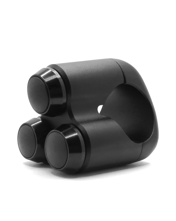
Handlebar switch · 3 buttons
Three independent momentary push buttons on a CNC aluminium mount for 22 mm handlebars. One for each job: auxiliary lights, horn, flash-to-pass,...